5×4 Photoresistor Camera
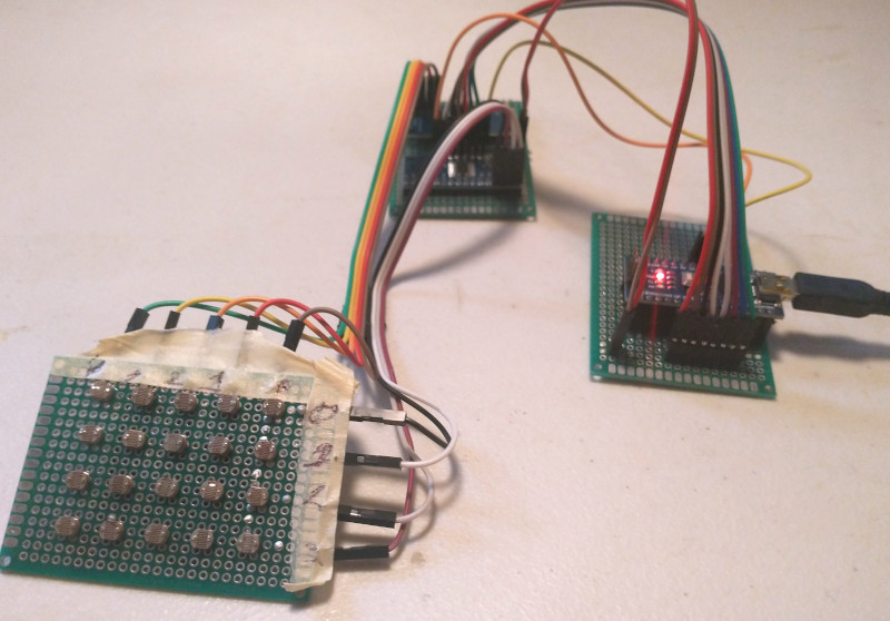
I had the idea to make a simple digital camera using a bunch of photoresistors. And a week or so later, I had built it! Here’s the jumble of circuit boards that’s the result of it
I will explain
The basic idea behind it
A photoresistor is an electronic component that has a lower resistance when more light is applied to it. The photoresistor can be hooked up to a microcontroller to measure the quantity of light. A grid of photoresistors would act like a grid of pixels in a camera. The brightness of each pixel could be measured by a microcontroller to create an image.
So, the goal is to have a grid of photoresistors, all measured by a microcontroller, to create an image where the brightness of each pixel is determined by the resistance of the each photoresistor.
Measuring the brightness of a single photoresistor
A photoresistor’s resistance varies with intensity of light shining on it. Resistance can not be directly measured, instead the voltage across the photoresistor must be measured. I’ll be using an Arduino Nano setup as follows to measure the voltage

The Arduino measures the voltage drop across R1 which varies as a result of a change in resistance of R2. I won’t go into all the algebra of this, partly because it’s boring and partly because I’m not certain of all the details. If you’re interested it the details, you should be able to solve for the resistance of the photoresistor using Ohm’s law and Kirchhoff’s voltage law.
Measuring the brightness of many
It would reasonably scale that, for each additional pixel, an additional resistor and analog input would be needed. The problem with this approach is that my microcontroller, an Arduino Nano, has only eight analog inputs. An eight pixel camera is very underwhelming so instead I chose to use the multiplexed matrix approach instead.
A matrix in this case (I’ll get to the multiplexed bit in a moment) consists of four rows and five columns of photoresistors. For any given photoresistor, the negative1 lead is soldered to the negative leads of the photoresistors on the same row and positive lead for any given photoresistor is soldered to the positive leads of the photoresistors on the same column. The circuit diagram for this arrangement looks as follows

Only two wires can be connected to the matrix at any moment: one on a row, and one on a column. The circuit formed by the two wires will go through the resistor where the column and row intersect. For example, if a wire is connected to column 2, and another is connected to row 3, the path between them would create a connection to resistor 18 . Likewise, column 3 and row 3 would yield resistor 19.
By selecting which row, and which column is connected, all photoresistors can be measured with just two wires, solving the limited analog input problem. However it is very impractical to have to manually rewire the circuit each time a picture is to be taken, and this is where the analog multiplexers come in. Instead of rewiring each row and column manually, the rows are wired to a multiplexer and the columns are wired to a multiplexer. A multiplexer has many inputs, but only one selected output. A binary number input to the multiplexer will select which input to ‘rewire’ to the output.
With the multiplexers, the circuit diagram now looks as follows

Each row is wired to the row multiplexer, and each column is wired to the column multiplexer. Each multiplexer has four digital input lines (4 bits) which selects the active input. As well as measuring the resistance of the photoresistor, the microcontroller controls which photoresistor is being measured at any time by sending a binary number through the four digital inputs (bits) of each multiplexer. The arrangement of matrix-and-multiplexer allows the use of eight digital pins2 and one analog pin in the place of twenty analog input pins. You may notice each multiplexer has sixteen inputs. Clearly I only need five inputs on each one, but the only commonly sold ones were of eight channels, or sixteen channels3. The sixteen channel multiplexers were a similar price, so I bought them.
Now that we have a reasonable way to read the value of twenty photoresistors, the camera can all be put together.
Final assembly
To finish off the hardware side of the camera, the measuring part and the multiplexer must be put together. Luckily, the signal lines from the multiplexer can be slotted right into where the single photoresistor is on the previous measuring setup. After that, the digital pins on one multiplexer must be wired to the lower four pins of a PORT4 and the other pins of the other multiplexer are wired to the upper four pins of the same PORT. Finally, power is wired up to the multiplexers.
With all that wiring, the circuit diagram now looks as follows

The only step left was to write the software to make it all work. I had in mind a three layer software stack. The first layer runs directly on the microcontroller. It selects each matrix-multiplexed photoresistor, measures the light from each, and then sends the data over serial to the next program. Layer two receives the serial message, parses it and saves the data to a JSON file. Finally, the third layer loads the JSON5 file on an interval and renders the intensity of each photoresistor as the brightness of a pixel on a grid.
Microcontroller layer
The microcontroller listens on serial over USB for a signal indicating it should capture a picture. When it receives the capture-image-signal, it switches the multiplexers though each photoresistor, and measures the voltage at it. After measuring all photoresistors, the microcontroller sends out each pixel value over serial, and waits for the next capture signal. I wrote this layer in the Arduino IDE, which really is just C++.
Serial receive layer
On the computer, the receive layer connects to the microcontroller over serial and requests picture. Upon receiving the data back from the microcontroller, the receive layer parses it into numbers and stores it as JSON in a file. This process repeats. I wrote this layer in Rust. It’s definitely the most buggy part of the stack. I was running out of time after spending the entire morning (and good part of the afternoon) soldering, so I rushed through this part. Sometimes the program doesn’t receive the data from serial correctly, but a restart of the program fixes the problem.
Display layer
I could have had the receive layer and the display layer in the same program, but I’m more familiar doing visual stuff in JavaScript, and I was running out of time as I said before, so I broke the visual component off into this layer. This layer is by far the simplest out of the three. It requests the JSON data file and then draws the pixel data onto a canvas in a loop.
Reflections

I made this project in a few hours and I definitely cut corners. I’m glad it worked, and it worked about as well as I thought it would. You can’t really take a picture of anything with it. Even if it did have enough resolution to capture a detailed image, I would need some kind of lens to focus the image on the sensor. Even then, I didn’t at all calibrate the sensor, either in software or in hardware. I suppose I wanted to see if it would be possible to build such a homebrew camera sensor, and I now think it is.
While I can’t promise anything, I’m considering making a full out 16×16 photoresistor camera with a lens and everything. I’d like to be able to take a real picture with it. I would need a custom PCB to avoid multiple days of soldering, and after doing the CAD for this post, I think I could design one. I would also need to build or buy a lens to focus light on the board. I’m not sure what kind of lens I would use to focus onto a 3in×3in sensor, but I’ll have to look into that.
While writing this post, the sensor broke. I’m not sure if it’s because of the broken solder joints, or the fact that I ran -5V through the multiplexers accidentally, but it’s a bricked now :)
-
Photoresistors don’t have a positive or negative side: they’re nonpolar. Negative and positive in this case are used in the place of “one wire” and “the other wire” for clarity. ↩︎
-
Four digital pins per multiplexer are only needed if all sixteen channels are being used. In this case, only five digital pins are needed (two for rows, three for columns). ↩︎
-
With two sixteen channel multiplexers, a 16×16 matrix could be made, which would be 256 photoresistors and an unbearable day of soldering. ↩︎
-
On an Arduino, a PORT is eight pins that are represented in software as a series of eight bits: an eight bit integer. ↩︎
-
JavaScript Object Notation: a generic data filetype which is both readable by humans and parsable by computers. ↩︎